Project Introduction
Frameoko started as a way to create an enclosure for a Shapeoko 4 Standard with a Shapeoko 4 Standard. What makes this approach different is that Frameoko is only the structural part of the enclosure, you get the freedom to choose what you want to enclose your machine in. Whether that’s optimized for sound, dust collection, maybe even machine visibility, this is up to you. At first I wanted to design Frameoko with 2 main criteria, It can be created with the stock 0.25″ upcut endmill that ships with the Shapeoko 4 Standard, and that the entire enclosure frame can be milled out on the same machine the enclosure is designed for.
Design Process
I started this project by laying out what it would take to get from start to finish through a flow chart + timeline visual I made in Obsidian’s built-in canvas editor. I included an estimate of how long each step would take, around 40% into the project. I realized that I severely underestimated the average per panel machining time + machine setup and file preparation in CAM.

Obsidian – Download
10%(Research + Ideation)
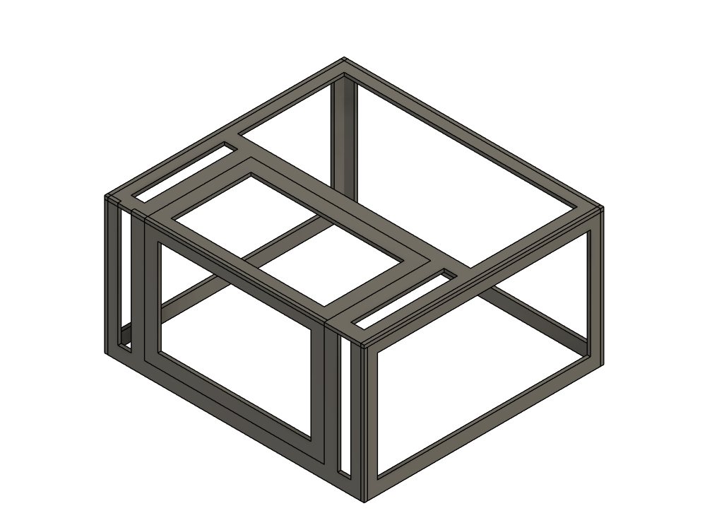
I just wanted an enclosure for my CNC, I was hoping I could find an enclosure somewhere online with free CAM files that I could just plop into carbide motion and be done. This was not the case, instead I wasn’t able to find a single flat packed enclosure for my machine and some of the other Shapeoko machines. With this research now concluded I had a good idea of what I wanted my enclosure to be so I began with some machine measurements and some basic 3D models. This is the design I went with, a simple shape with an access door that wraps from the top to the front and enclosure the machines footprint with some clearance on all sides:
25%(Cleaning 3D model + materials)
With a design now chosen the next task was to break it up into segments that are small enough that the machine could mill out. I did some research on how I wanted everything to come together. I wanted to make the frame very easy to assemble with just a bottle of wood glue and possibly a dremel for some light post processing. So I made every segment connect with circular lap joints that can be snapped together easily and leave a flush surface for the enclosure material.
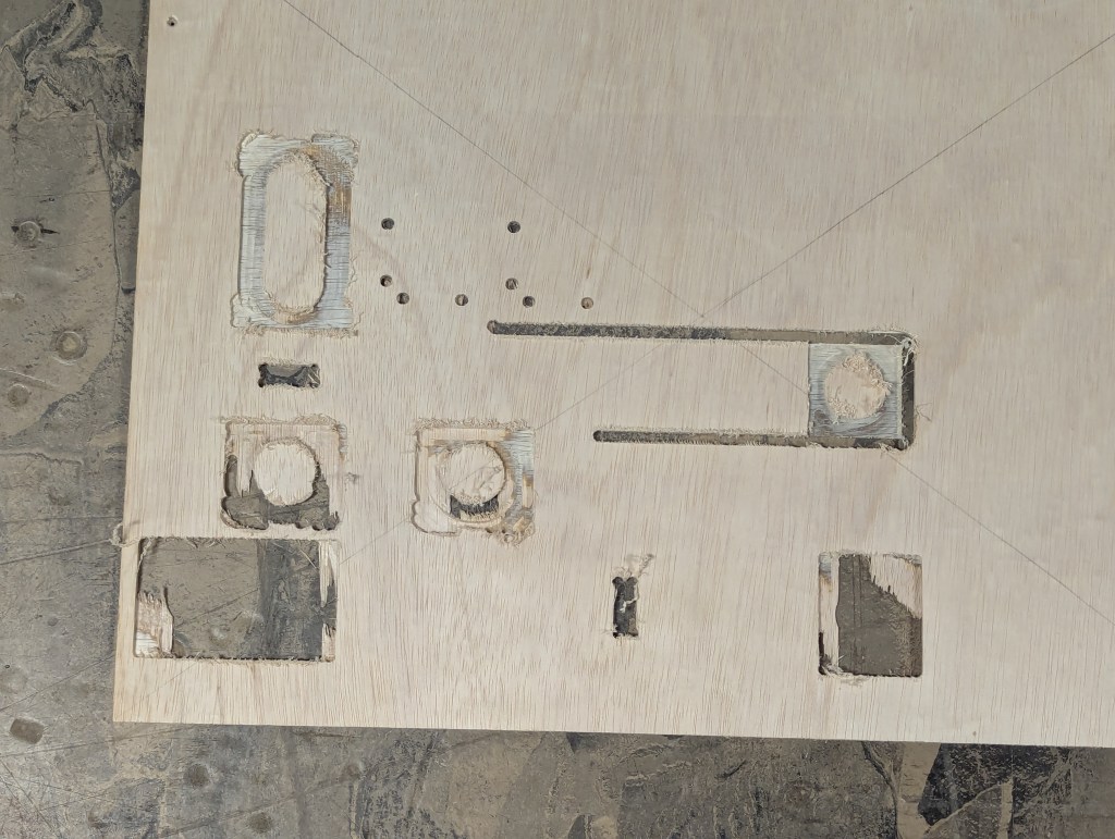
For wood, I chose lauan project panel at first (TERRIBLE IDEA) since it was the right size and was fairly cheap per panel. The segments I wanted were 0.25″ thick and this project panel was slightly less than .25 which had some side effects when I set my z origin during a test cut. Because the model was pretty much shifted down no part had proper tabbing so things went flying. On top of this the materials tearout was really bad and I was now conflicted to either remodel the entire enclosure or start fresh with a fully parametric design. I decided to remodel the Frameoko all together now parametrically.
A parametric Frameoko is even better, This made Frameoko not just limited to a Shapeoko 4 Standard but any other CNC machine, or any other machine that needs an enclosure.
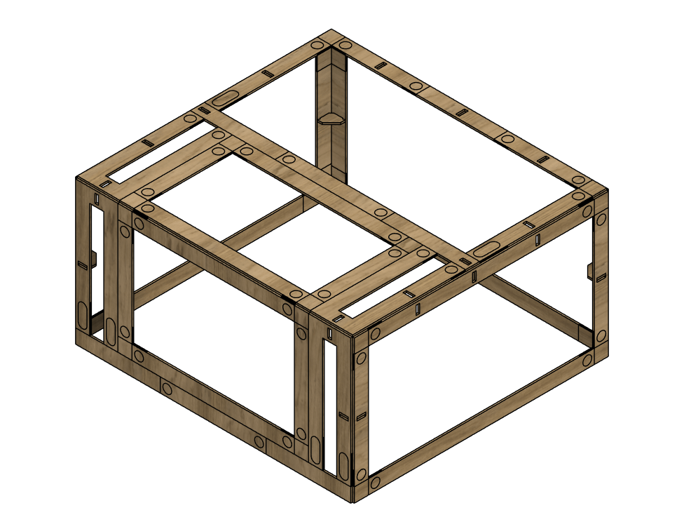
Redesigning the Frameoko was a pleasant experience, I now have a habit of parametric modeling. Previously to this I hadn’t really touched the parameters tool in Fusion and enjoyed the iterative process of making some changes and testing if they morph as intended when the parameters are changed. This presented some unique design challenges, generating the proper amount of segments was difficult because not only do they need to fit inside your specified cut area but they also must alternate between a negative and positive lap joint. I reached a point where the file was so parameter dense that changing one would crash Fusion. There is likely a way around this, I’m thinking I should split up my main sketches into multiple ones for different operations but I’m not sure. The Frameoko at this point was at a kind of stand still but the file was developed enough to where I could start to arrange the segments into panels that I could throw into CAM.
Also I found a much better material alternative, 0.25″ x 12″ x 18″ solid MDF sheets at Home Depot that were perfect. The actual cut area of a Shapeoko 4 Standard is around 17″x17″ so there is still some space for a larger sheet but this size is just convenient enough to throw onto your Shapeko without the need of a table saw to cut the stock down to size.
Home Depot – MDF wood
50%(prep CAM files + run the cuts)
I prepped all the files in Fusions built in CAM workspace. To do this I had to make separate files for each segment or joint sheet which took some time(definitely will change this for V2). I would say on average each panel took ~1hr of machining time and ~5min of setup of your workholding by screwing your stock down like me. The cuts went well, there were only a few minor issues like poor cutting quality and machining accuracy.

In total these are the rough machining time + costs for a Frameok V1 for a Shapeoko 4 Standard:
– total panels = ~25
– total cost = ~$100
– total machining time = ~25hrs
I used more material than expected so something I’m aiming for in V2 is a Frameoko that’s less resource hungry.
75%(final assembly)
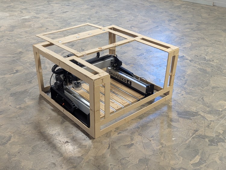
Assembly was the weakest part of the project, I aimed to make the Frameoko easy to assemble but because of the slight imperfections in my CNC’ing setup faces were misaligned and joints/ribs needed to be heavily sanded. The top face was challenging because I didn’t include any rib slots on the top LR side since they would have to cut through the F joints which I did not like because of the complexities it would have added in CAD and possibly CAM as well. To solve this I removed 1 of the slots on the 2 top ribs so the top is still being supported but it’s really just resting on the 2 ribs fixed to the LR sides.
The access door was also challenging because of the hinge screw protruding from the back of the MDF and the door being slightly out of alignment with the top and front doorframes.


100%(completion + V2 notes)
So this was my process from start to finish, throughout this process I realized what I really have to watch out for when maintaining my machine. The biggest factor in the quality of the final Frameoko is the tolerance between joints. I had to do a significant amount of post processing which made the top and front faces and the access door all slightly longer or shorter than they needed to be. Just enough to cause some jank. So for future builds ill know to make sure of these things:
– belts are properly and equally tensioned
– machine is trammed
– tolerances are correct in CAD
– v rails are kept clean
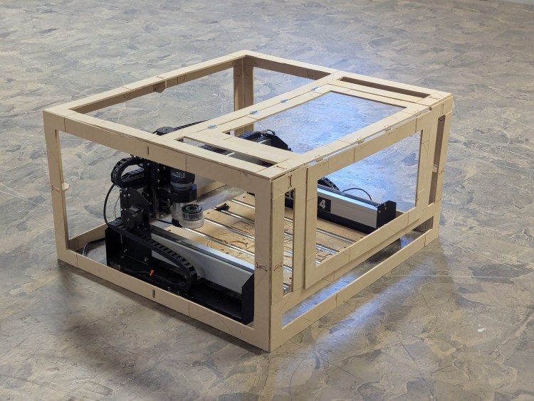
maybe that list helps someone out but anyways take a look at V1:


I can’t wait for V2! All of the files will be uploaded to a github repo of mine, and a fully parametric model will also be attached shortly(have to find a way around fusion crashing).
Github – Frameoko
If you’ve made it here thanks for the interest in my process and maybe also this project. If you would like to keep browsing I highly recommend the previous article!
